Download
Ver. 1.0.0
for R2023a
Other version
This model is a simulation model designed for evaluating turning performance and ride comfort of BEVs (Battery Electric Vehicles). It is utilized in our educational service, digital development exercises.
 The oval course is equipped with bumps, allowing for the measurement of roll angle and vertical acceleration to evaluate ride comfort.
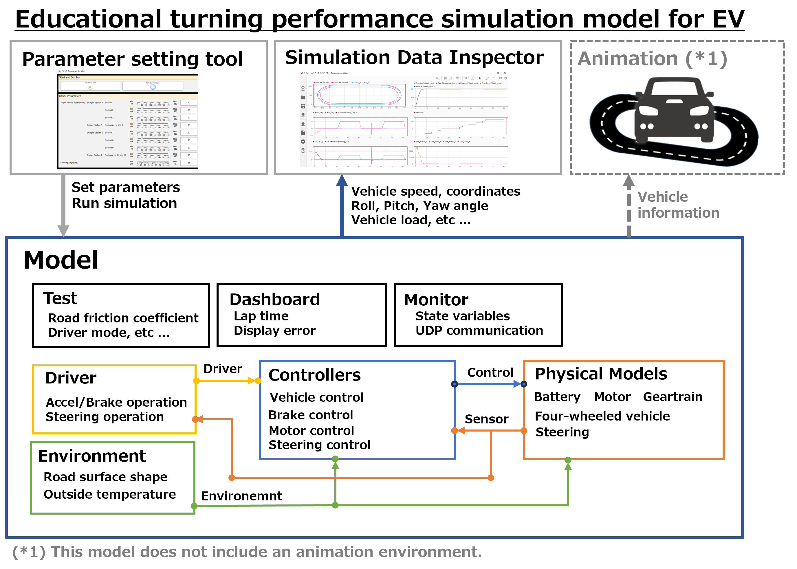
The overall vehicle configuration consists of road environment, driver, control, and vehicle physical models. The control system is composed of vehicle dynamics and driving control, as well as various unit controls. The vehicle physical model includes the battery, motor, inverter, vehicle (a 3-axis, 6-degree-of-freedom vehicle model), and steering.
List of signals:
- Driver Signals
Accel operation, Brake operation, Steering Angle
- Control Signals
Control brake operation(Front wheels, Rear wheels),Control steering angle
Back electromotive force coefficient, Motor control current
Motor fault determination
- Environment Signals
Outside temperature, Road surface friction coefficient
Road surface bump(Front wheels, Rear wheels)
- Sensor Signals
Vehicle coordinates(X, Y, Z), Yaw angle, Roll angle, Pitch angle
Vehicle speed, Wheel speed (4 Wheels), Motor rotation speed
Battery SoC (State of Charge), Battery voltage
Temperature (Battery cells, Inverter, Motor)
Power consumption (AC, Battery, Inverter, Motor)
* In this model, the x, y and z-axis direction is defined Vehicle Cartesian coordinate system. (The positive direction of the x-axis is to the front of the vehicle, the positive direction of the y-axis is to the left of the vehicle, and the positive direction of the z-axis is to the top of the vehicle.) For roll, pitch, and yaw are defined in right-handed coordinates.
How to connect :
Internal configuration diagram :
Operating environment :
Block diagram :
The block diagram of the vehicle control(Controllers) and vehicle physical model (Physical Models)
Solver settings :
- Global solver
- Solver: ode1be (Iteration number : 1)
- Sample time: 1.0 msec
- Solver: ode1be (Iteration number : 1)
- Sample time: 1.0 msec
Model constraints :
- This model does not simulate or guarantee the behavior and behavior accuracy of the actual machine.
- This model does not support code generation or rapid accelerators.
- If the file structure in the library folder is changed, this model does not work.
- It may not work with other operating environments or solver settings than those listed above.
- It may not work with parameter sets other than those provided.
- The initial state is a stopped state (initial speed: 0 [m/s]).
How to execute :
1. Set the folder containing the library file to MATLAB current directory.
2. Read the parameter file.
3. Open the execution target model.
4. Run the model.
5. Check the results using the Simulation Data Inspector.
6. Change the parameters using the Parameter setting tool.
2. Read the parameter file.
3. Open the execution target model.
4. Run the model.
5. Check the results using the Simulation Data Inspector.
6. Change the parameters using the Parameter setting tool.
Download
Ver. 1.0.0
for R2023a
Other version
Other version


